Notes
Notes and Website created by Pushkal Vashist and Daniel Yong because we are sigma. Have fun studying!
This topic covers how devices communicate on a local network using Layer 2 addresses and the rules that govern this communication.
Q1) The Purpose of a Switch MAC Address Table
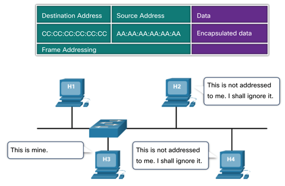
A Layer 2 Ethernet switch uses a MAC address table (also known as a Content Addressable Memory or CAM table) to make intelligent forwarding decisions. Its primary purpose is to avoid network congestion by sending frames only to the specific port associated with the destination device, rather than broadcasting every frame to every port. A switch stores information about the other Ethernet interfaces to which it is connected on a network. By maintaining the MAC address table, switches make forwarding decisions based on MAC addresses, allowing them to forward frames directly to the appropriate destination port. This process reduces unnecessary network traffic and improves the overall efficiency of the network.
How it works: The switch learns the MAC addresses of devices connected to its ports and stores this information in the MAC address table.
Structure: The table is a simple two-column list: Port and MAC Address.
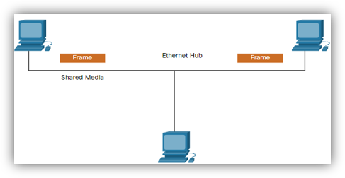
Benefit: Unlike a hub which forwards incoming data out of all other ports (creating collisions and unnecessary traffic), a switch consults its MAC address table. If the destination MAC address is in the table, the switch creates a direct connection and forwards the frame only to the corresponding port. This isolates traffic and improves network performance significantly.
Q2) The Switch Learning and Forwarding Process
Let's trace the process when PCA sends a frame to PCD, and PCD replies, to see how the MAC address table is populated.
Scenario: PCA (MAC 00-0A on Port 1) sends a frame to PCD (MAC 00-0D on Port 4). The switch has just been powered on, and its MAC address table is empty.
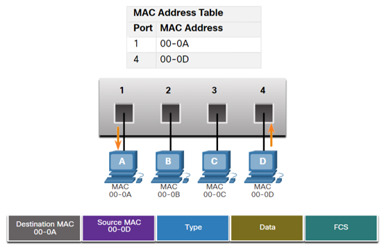
Step 1: PCA Sends a Frame to PCD
- Examine Source MAC: The switch receives the frame on Port 1. It examines the source MAC address of the frame, which is 00-0A.
- Populate Table: The switch sees that 00-0A is not in its table. It adds an entry, associating PCA's MAC address with the port it came in on.
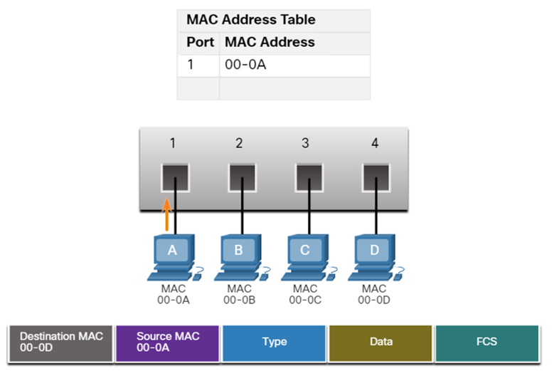
- Find Destination MAC: The switch then looks at the destination MAC address, which is 00-0D. It searches its table for this address.
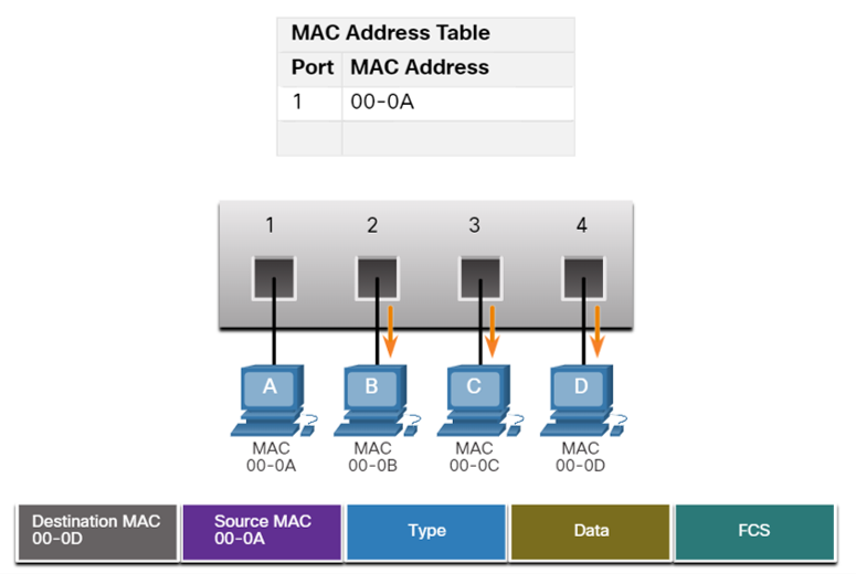
- Flood Frame: The switch does not find an entry for 00-0D. Because it doesn't know which port leads to PCD, it performs a process called flooding. It forwards the frame out of all ports except the incoming port (Port 1). Therefore, the frame is sent to Ports 2, 3, and 4.
- Device Response: PCB and PCC receive the frame, see that the destination MAC is not their own, and discard it. PCD receives the frame, recognizes its own MAC address, and processes it.
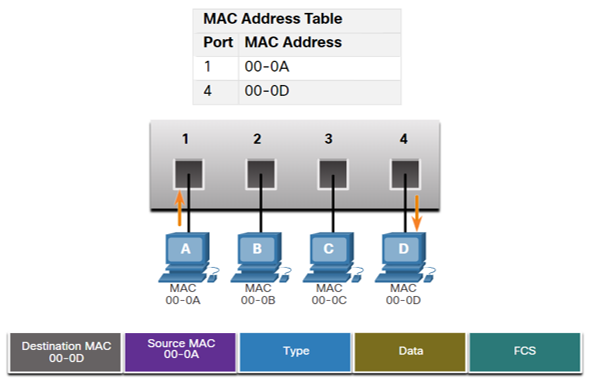
Step 2: PCD Replies to PCA
- Examine Source MAC: PCD sends a reply frame destined for PCA. The frame enters the switch on Port 4. The switch examines the source MAC address of this new frame, which is 00-0D.
- Populate Table: The switch adds a new entry for PCD.
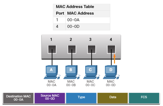
- Find Destination MAC: The switch looks at the destination MAC address, which is 00-0A. It searches its table and finds a match.
- Forward Frame: The table indicates that 00-0A is located on Port 1. The switch now forwards the frame only out of Port 1. It does not flood the frame to other ports.
Step 3: PCA Sends Another Frame to PCD
- Refresh Source MAC Timer: The switch receives the frame on Port 1 from PCA and resets the 5-minute timer for MAC 00-0A.
- Destination MAC Found: The table already has PCD’s MAC 00-0D mapped to Port 4.
- Filter & Forward: The switch filters the frame and forwards it only out Port 4 (no flooding).
Conclusion: At the end of this exchange, the switch has learned the locations of both PCA and PCD, and future communication between them will be efficient and direct.
Q3) Half-Duplex vs. Full-Duplex Communication
This describes the direction of data transmission between two devices.
| Feature | Half-Duplex Communication | Full-Duplex Communication |
|---|---|---|
| Data Flow | Data can flow in both directions, but not simultaneously. Only one device can send at a time. | Data can flow in both directions simultaneously. Both devices can send and receive at the same time. |
| Analogy | Walkie-talkies. You have to say "over" to signal that it's the other person's turn to speak. | A telephone conversation. Both people can speak and listen at the same time. |
| Collision Domain | Devices share a single collision domain. Collisions can occur if two devices transmit at once. | Each device has a dedicated link. Collisions are eliminated. |
| Common Use | Legacy Ethernet hubs, bus topologies, and Wi-Fi (WLANs). | Modern Ethernet switches. This is the default mode for most wired network connections today. |
Media Access Control Methods
Multiaccess networks are networks where two or more devices may attempt to access the network at the same time. Because multiple devices share the same medium, rules are needed to coordinate access and prevent collisions. There are two main types of access control methods: Contention-based and Controlled access.
1. Contention-Based Access
In contention-based networks, all nodes share the same medium in half-duplex mode, meaning only one device can transmit at a time. Devices compete for the medium, and access is not predetermined.
CSMA: Carrier Sense Multiple Access
- Carrier Sense: A device listens to the medium before transmitting to check if it is busy.
- Multiple Access: Many devices share the same medium and have equal access opportunities.
If the medium is idle, the device transmits. If it is busy, the device waits a random amount of time before trying again.
Collision Handling in CSMA
- CSMA/CD (Collision Detection): Used in legacy wired Ethernet. Devices detect collisions while transmitting, stop, send a jam signal, and retry after a random backoff.
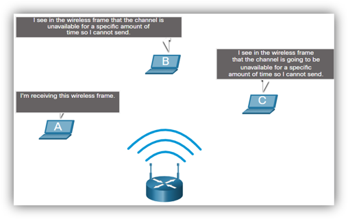
- CSMA/CA (Collision Avoidance): Used in wireless LANs. Devices announce intent to send before transmitting. The receiver sends an ACK; if not received, the sender retries.
2. Controlled Access
In controlled-access networks, each device is assigned a turn to transmit. This deterministic approach avoids collisions but can be inefficient when devices have no data to send.
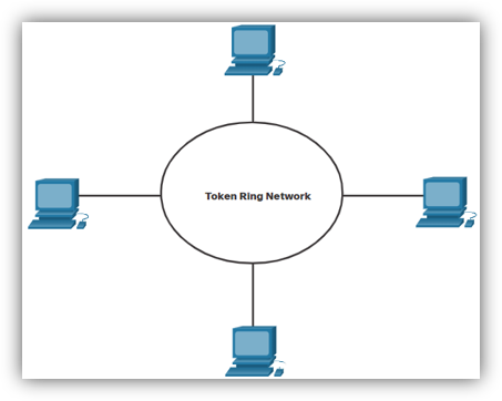
Token Ring Network
Devices form a logical ring, and a special frame called a token circulates. A device may only transmit if it holds the token. Once it finishes sending data, it releases the token for others to use. Because only one device holds the token at a time, collisions cannot occur. However, efficiency can drop since devices must wait their turn even if the medium is idle.
Topics 6, 8: IPv4 Addressing & Subnetting
IPv4 Address Fundamentals
Purpose: An IPv4 address is a logical 32-bit address that uniquely identifies a host on a network, allowing communication across different local networks via routing.
Structure:
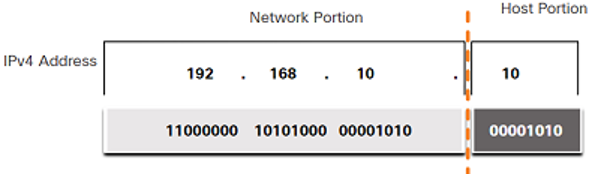
- 32-Bits: Represented as four 8-bit bytes called octets.
- Dotted-Decimal Notation: Each octet is converted to its decimal value and separated by a period (e.g., 192.168.10.1).
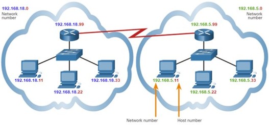
- Two Parts: Every IPv4 address has a Network Portion (identifies the network, identical for all hosts on it) and a Host Portion (identifies a specific device, must be unique within the network).
The Subnet Mask
Purpose: A 32-bit value that differentiates the network portion from the host portion of an IPv4 address.
How it works: It's a sequence of consecutive 1s (representing the Network Portion) followed by 0s (representing the Host Portion).
Prefix Length (Slash Notation): A shorthand for the subnet mask, indicated by a forward slash (/) followed by the number of 1s (e.g., /24 is 255.255.255.0).
 Subnetting: The Why and
How
Subnetting: The Why and
How
Why Subnet?
- Reduce Broadcast Domain Size: Limits broadcast traffic to smaller subnets, improving performance.
- Improve Performance: Reduces overall network traffic.
- Implement Security: Allows for policies to control traffic flow between subnets.
How it Works: Subnetting divides a large network into smaller ones by "borrowing" bits from the host portion to use as network bits, thus increasing the prefix length.
Essential Subnetting Formulas
Given a prefix length /N:
- Number of Network Bits (N): Given by the prefix length.
- Number of Host Bits (H): H = 32 - N
- Number of Subnets Created: 2^B (where B is the number of borrowed bits).
- Number of Usable Hosts per Subnet: (2^H) - 2 (subtracting the all-0s network address and the all-1s broadcast address).
Tutorial 6 Walkthrough: Finding Network Information
Example: 192.168.10.234 with mask 255.255.255.0.
- Identify Prefix: The mask 255.255.255.0 is a /24 prefix.
- Find Network and Host Bits: N = 24, H = 32 - 24 = 8.
- Find the Network Address: With a /24 mask, the first three octets are the network. The address is 192.168.10.0.
- Find the Broadcast Address: Set all host bits (the last octet) to 1. The address is 192.168.10.255.
- Find the Number of Hosts: (2⁸) - 2 = 254 usable hosts.
- Find the Valid Host Range: 192.168.10.1 to 192.168.10.254.
Types of IPv4 Addresses
- Public vs. Private: Public addresses are globally routable on the internet; private addresses are for internal networks and require Network Address Translation (NAT) for internet access.
- RFC 1918 Private Ranges:
- 10.0.0.0/8 (10.0.0.0 to 10.255.255.255)
- 172.16.0.0/12 (172.16.0.0 to 172.31.255.255)
- 192.168.0.0/16 (192.168.0.0 to 192.168.255.255)
- Special Use Addresses:
- Loopback Address: 127.0.0.1 for self-testing.
- Link-Local (APIPA): 169.254.0.0/16, self-assigned if a DHCP server is unreachable.
Topics 7, 11: ARP, Gateways, and Routing
Q2) Address Resolution Protocol (ARP)
Purpose: ARP is a communication protocol used to discover the Layer 2 (MAC) address associated with a Layer 3 (IPv4) address. This is critical because Ethernet frames require a destination MAC address for delivery on a local network.
ARP Process:
- A host knows the destination IP address but not the MAC address.
- The host sends a broadcast ARP Request to the local network, asking "Who has IP x.x.x.x?".
- Every device processes the request, but only the device with the matching IP responds.
- The target device sends a unicast ARP Reply directly back, providing its MAC address.
- The original host caches this IP-to-MAC mapping in its ARP cache for future use.
Q1) The Default Gateway
Features/Purpose: A default gateway is a network node (usually a router) that acts as an access point to other networks. It is the "doorway" for traffic to exit the local network.
It has a local IP address within the same range as other hosts on the network. It routes traffic destined for other networks. A device cannot communicate outside its local network without a configured default gateway.
How it's Used:
- When a host sends a packet, it checks if the destination is local or remote.
- If local: It uses ARP to find the destination host's MAC and sends the frame directly.
- If remote: It uses ARP to find the MAC address of its default gateway and sends the frame there. The destination IP in the packet remains the ultimate destination.
Q4) Broadcast Domain
A broadcast domain is a logical area of a network where a broadcast frame sent by one device will be received by all other devices in that same segment. Switches forward broadcasts and thus extend broadcast domains. Routers do not forward broadcasts, effectively segmenting a network into multiple, smaller broadcast domains.
Q5) How many broadcast domains?
To count broadcast domains, count the number of active router interfaces in the topology, as each one creates a boundary for broadcasts. In the Tutorial 7, Q5 diagram, there are three distinct networks connected by routers, therefore, there are THREE broadcast domains.
Routing Tables and Packet Forwarding
A router's primary job is to forward packets between networks using a routing table.
Router Packet Forwarding Decision:
- A router receives a frame, de-encapsulates it, and examines the packet's destination IP address.
- It searches its routing table for the route with the longest prefix match. This is the most specific route to the destination.
- If a match is found, the router re-encapsulates the packet and forwards it out the specified interface.
- If no match is found, it uses the default route (if configured).
- If no match and no default route exist, the packet is dropped.
Types of Routes (Q10):
- Directly Connected Routes (C, L): Automatically added for active router interfaces.
- Static Routes (S): Manually configured. They are secure but not adaptable to network changes.
- Dynamic Routes (e.g., O for OSPF): Learned automatically from other routers via routing protocols. They are adaptable but require more resources.
- Default Static Route (S*): A route of last resort (0.0.0.0/0) that directs all traffic for which no specific route is known, typically towards the internet.
Topic 10: Network Layer
Four Basic Functions (Q1):
- Addressing end devices: Assigning unique IP addresses (IPv4/IPv6).
- Encapsulation: Adding an IP header to a Transport Layer segment to create a packet.
- Routing: Selecting the best path to direct packets to their destination.
- De-encapsulation: Removing the IP header at the destination to pass the segment to the Transport Layer.
Characteristics of IP Protocol (Q2):
- Connectionless: No prior connection is established; each packet is independent.
- Best Effort: IP does not guarantee delivery; reliability is handled by upper layers like TCP.
- Media Independent: IP operates independently of the physical media (copper, fiber, wireless).
Fragmentation in IP (Q3):
If a router must forward an IPv4 packet to a network with a smaller Maximum Transmission Unit (MTU), it breaks the packet into smaller pieces, a process called fragmentation. Importantly, routers can fragment IPv4 packets, but not IPv6 packets; in IPv6, the source host must handle fragmentation.
IPv4 vs. IPv6 Header Fields (Q4, Q5, Q6, Q7)
The IPv6 header is simpler and more efficient than the IPv4 header.
- Fields kept (or have an equivalent): Version, Source Address, Destination Address, Differentiated Services (-> Traffic Class), Time to Live (-> Hop Limit), Protocol (-> Next Header).
- IPv4 fields removed: Internet Header Length (IHL), Identification, Flags, Fragment Offset, and Header Checksum. The checksum was removed to improve performance as other layers already perform error checking.
- New IPv6 fields added: Flow Label, a 20-bit field to identify packets in the same flow for consistent Quality of Service (QoS) handling.
Topic 9: IPv6
Why transit to IPv6? (Q1)
- IPv4 Address Depletion: The primary driver. There are not enough IPv4 addresses for the growing number of internet-connected devices.
- Improved Packet Handling: A simplified header allows for more efficient processing by routers.
- Eliminates the Need for NAT: The vast address space allows every device to have a unique public IP, restoring end-to-end connectivity.
Characteristics of an IPv6 Address (Q2):
- 128 bits in length.
- Represented as eight groups (hextets) of four hexadecimal digits, separated by colons.
Compressing IPv6 Addresses (Q4):
There are two rules:
- Omit Leading Zeros: Within any hextet, leading zeros can be removed (e.g., 0db8 becomes db8).
- Double Colon (::): A single, contiguous block of all-zero hextets can be replaced by a double colon (::). This can only be used once per address.
Types of IPv6 Addresses (Q6):
- Unicast: Identifies a single interface.
- Global Unicast Address (GUA): The public, internet-routable equivalent of a public IPv4 address, typically starting with 2000::/3.
- Link-Local Address (LLA): Required for every IPv6-enabled interface, used for communication on the local link only. Not routable and starts with fe80::/10.
- Multicast: Sends a single packet to multiple destinations. Replaces broadcast in IPv6.
- Anycast: A unicast address assigned to multiple devices; packets are routed to the nearest one.
Topics 12 & 13: Transport & Application Layers
Topic 12: Transport Layer
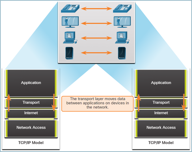
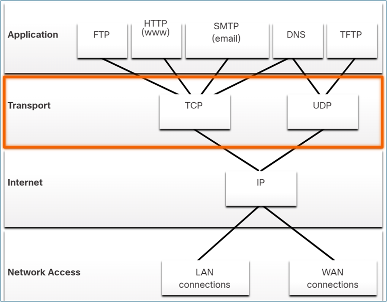
Role of the Transport Layer
The Transport Layer is responsible for the logical communication between applications running on different hosts. It acts as the crucial link between the application layer and the lower layers that handle network transmission. Its primary role is to ensure that data generated by an application on one device is successfully delivered to the correct application on another device.
Key responsibilities of the Transport Layer include:
- Tracking Individual Conversations: It manages and tracks multiple data flows between applications on source and destination hosts separately.
- Segmenting Data and Reassembling Segments: It breaks down large application data into smaller, manageable pieces called segments (for TCP) or datagrams (for UDP). The receiving host's transport layer then reassembles these pieces back into the original data stream.
- Adding Header Information: It adds a header to each segment or datagram containing control information, such as port numbers, sequence numbers, and checksums.
- Identifying Applications: It uses port numbers to identify the specific source and destination applications for a conversation.
- Conversation Multiplexing: It enables multiple applications to communicate over the network simultaneously by interleaving their data segments onto the same network connection.
Transport Layer Protocols: TCP and UDP
The Transport Layer includes two primary protocols to meet the diverse reliability requirements of different applications:
- TCP (Transmission Control Protocol): A reliable, connection-oriented protocol that ensures the complete and ordered delivery of application data.
- UDP (User Datagram Protocol): A simple, connectionless protocol that provides fast, low-overhead data delivery without guarantees.
Transmission Control Protocol (TCP)
TCP is a full-featured protocol designed for applications where reliability is more important than speed. It establishes a connection before sending data and includes mechanisms to manage data flow and handle errors.
TCP Features
- Establishes a Session: TCP is connection-oriented, meaning it sets up a session between the source and destination devices using a three-way handshake before any data is sent.
- Ensures Reliable Delivery: It guarantees that every segment sent by the source will arrive at the destination by tracking transmissions and requiring acknowledgments from the receiver. Lost segments are retransmitted.
- Provides Same-Order Delivery: TCP numbers and sequences all segments, allowing the destination to reassemble them in the correct order, even if they arrive out of sequence.
- Supports Flow Control: It manages the rate of data transmission to prevent the sending host from overwhelming the receiving host with too much data at once.
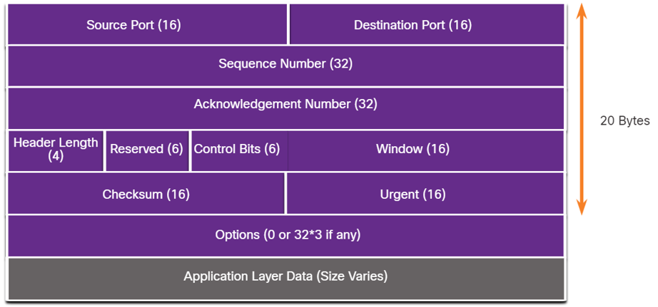
TCP Header
As a stateful protocol, TCP tracks the status of each communication session. To do this, it adds a 20-byte header to each segment.
| TCP Header Field | Description |
|---|---|
| Source Port | A 16-bit field identifying the source application's port number. |
| Destination Port | A 16-bit field identifying the destination application's port number. |
| Sequence Number | A 32-bit field used to reassemble data in the correct order at the destination. |
| Acknowledgment Number | A 32-bit field indicating that data has been received and specifying the next byte expected from the source. |
| Header Length | A 4-bit field indicating the total length of the TCP header. |
| Control Bits (Flags) | A 6-bit field containing flags (like SYN, ACK, FIN) that control the connection state. |
| Window Size | A 16-bit field used for flow control, indicating the number of bytes the receiver can accept. |
| Checksum | A 16-bit field used for error-checking the segment header and data. |
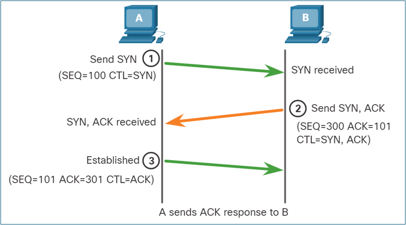
TCP Communication Process
Connection Establishment (3-Way Handshake):
- SYN: The client sends a SYN (synchronize) segment to the server to initiate a connection.
- SYN-ACK: The server responds with a SYN-ACK (synchronize-acknowledgment) segment to acknowledge the request and establish its own connection parameters.
- ACK: The client sends an ACK (acknowledgment) segment back to the server, and the connection is established.
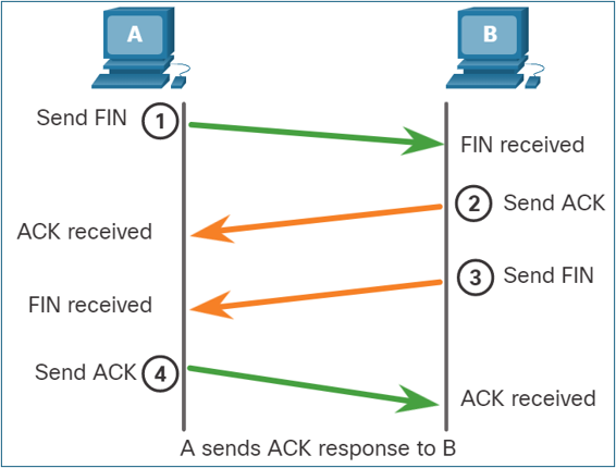
Session Termination: To close a connection, each host must use the two-way handshake consisting of a Finish (FIN) and an Acknowledgment (ACK) control flags. Therefore, a TCP conversation requires four exchanges to end both sessions.
- Host A has no more data to forward and sends a segment with the FIN flag set.
- Host B acknowledges Host A.
- Host B then sends a segment with the FIN flag set.
- Host A acknowledges Host B.
User Datagram Protocol (UDP)
UDP is a "best-effort" protocol used for applications where speed is critical and some data loss is acceptable. It is stateless, meaning it does not track the session or guarantee delivery.
UDP Features
- Data is reconstructed in the order it is received, with no reordering.
- Lost segments are not resent.
- No session is established before sending data.
- The sender is not informed about the receiver's resource availability.
UDP Header
The UDP header is much simpler than TCP's, with only 8 bytes of overhead. It contains just four fields: Source Port, Destination Port, Length, and Checksum.
Comparing TCP and UDP
| Feature | TCP | UDP |
|---|---|---|
| Connection | Connection-oriented; establishes a session with a 3-way handshake. | Connectionless; sends data without establishing a connection. |
| Reliability | High; guarantees delivery with acknowledgments and retransmissions. | Low; best-effort delivery with no guarantees or acknowledgments. |
| Ordering | Segments are sequenced and reassembled in the correct order. | Datagrams may arrive out of order and are not reordered. |
| Overhead | High (20-byte header). | Low (8-byte header). |
| Speed | Slower due to reliability and flow control processing. | Faster due to minimal overhead and lack of processing. |
| Use Cases | Web browsing (HTTP/HTTPS), file transfer (FTP), email (SMTP, IMAP). | Streaming (VoIP), online gaming, DNS, DHCP. |
Port Numbers and Sockets
Both TCP and UDP use port numbers to direct data to the correct application on a host. A socket is the combination of an IP address and a port number. A socket pair, consisting of the source and destination sockets, uniquely identifies a single network conversation.
Ports are managed by the Internet Corporation for Assigned Names and Numbers (ICANN) and are categorized as:
- Well-known ports (1–1023): Reserved for common services like HTTP (80), HTTPS (443), FTP (21), and SMTP (25).
- Registered ports (1024–49151): Assigned to user-installed applications or services.
- Private/Dynamic ports (49152–65535): Used for temporary client-side connections.
Topic 13: Application Layer
Application Layer Overview
The Application Layer in the TCP/IP model provides the interface between applications and the network. It combines the functions of the top three layers of the OSI model (Application, Presentation, and Session).
- Application Functions: Provides network services directly to software applications (e.g., HTTP for web browsers).
- Presentation Functions: Handles data formatting, compression, and encryption to ensure data from the source device is readable by the destination device. Examples include JPG, GIF, and MKV.
- Session Functions: Creates, maintains, and terminates dialogs between source and destination applications.
Key Application Layer Protocols
These protocols specify the format and control information necessary for common internet functions.
| Protocol | Description | Transport Protocol & Port |
|---|---|---|
| DNS (Domain Name System) | Translates human-readable domain names (e.g., www.google.com) into numerical IP addresses. | UDP 53 (for queries), TCP 53 (for zone transfers) |
| DHCP (Dynamic Host Configuration Protocol) | Automatically assigns IP addresses and other network configuration to devices on a network. | UDP 67 (Server), 68 (Client) |
| HTTP (Hypertext Transfer Protocol) | A set of rules for exchanging text, images, and other multimedia files on the World Wide Web. | TCP 80 |
| HTTPS (HTTP Secure) | The secure version of HTTP, which encrypts data for secure communication. | TCP 443 |
| FTP (File Transfer Protocol) | Transfers files between systems. It uses two separate connections: a control connection and a data connection. | TCP 21 (Control), 20 (Data) |
| SMTP (Simple Mail Transfer Protocol) | Used by email clients and servers to send email messages. | TCP 25 |
| POP3 (Post Office Protocol v3) | Used by email clients to retrieve email from a server, often removing it from the server after download. | TCP 110 |
| IMAP (Internet Message Access Protocol) | Used by email clients to retrieve email while keeping messages stored on the server, allowing access from multiple devices. | TCP 143 |
| Telnet | Provides remote command-line access to a server. It is insecure because data is sent in plaintext. | TCP 23 |
| SSH (Secure Shell) | Provides secure, encrypted remote command-line access. It is the recommended replacement for Telnet. | TCP 22 |
Practice Questions (MCQ & Multi-Select)
Suggest a New Question
Have an idea for a good practice question? Fill out the form below. Your suggestion will be reviewed by an administrator before being added to the quiz.
Structured Practice Problems
Answer the descriptive questions below. Your response will be graded by an AI.